
|
George KJ6VU |
Serial Macro Command Utility
This utility allows you to send serial commands to any COM port on your computer
After over 35 years in Silicon Valley we decided to pull up stakes and move to the greater Portland, Oregon area. The move will take several months from start to finish which means just about everything in the shack and on the workbench needed to be boxed up and moved into storage. But any self respecting ham and homebrewer needs to have some sort of station and workbench even if it all fits into a few nylon gear bags. In this blog I want to share my experience in coming up with a very compact portable station and workbench, share the list of essentials and what worked well and not so well. My hope is that you will find this interesting if not useful for your situation. Whether you living in a small apartment, traveling or relocating like me, there are times when having a compact bench comes in very handy.
THE PORTABLE WORKBENCH
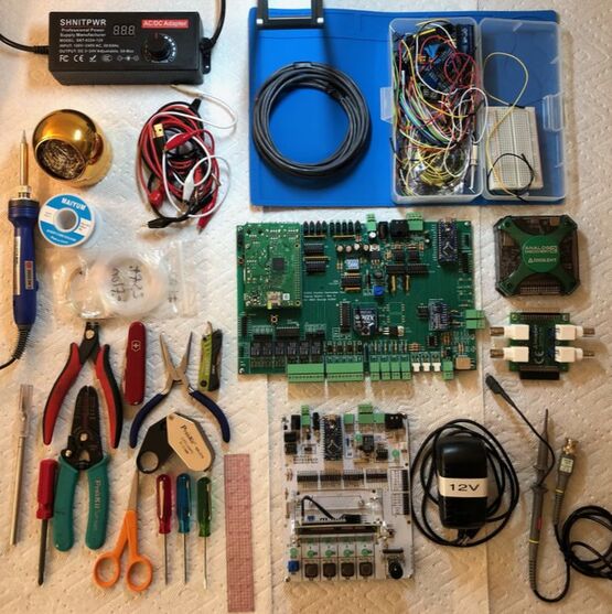
The obvious place to begin is the bag itself then the set of tools and other gear needed to build and test various projects. In my case, I have a few current projects based on Raspberry Pi and Arduino microcontrollers, so hardware for these projects are included in the basic bench.
|
|
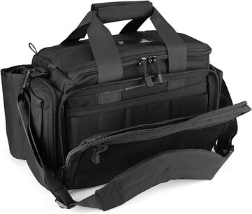
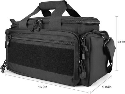
The entire portable workbench easily fits into a 17" x 10" x 10" nylon gear bag purchased on Amazon for about $55. I liked the bag so much I bought a second one for the portable station. PRO TIP: When searching for a good radio gear bag look for "range bags" or "EMS bags". Amazon Link
|
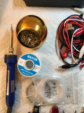
The Essentials can be broken down into a few categories.
|
|
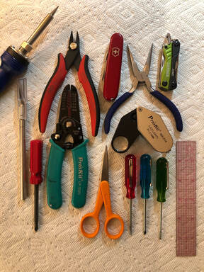
Basic Hand Tools
|
|
Soldering Equipment
|
Test Equipment (No detailed photo)
Digilent Analog Discovery II pocket USB connected test equipment puck. Features include:
- Fluke 101 or better portable DMM and test leads
- Banana plug to aligator clips and banana plug to EZ-hook leads
Digilent Analog Discovery II pocket USB connected test equipment puck. Features include:
- 2 channel oscilloscope
- Arbitrary waveform generator
- DC power supply (low current)
- Low frequency spectrum analyzer and network analyzer
- 16 channel digital input / output
- And more...
|
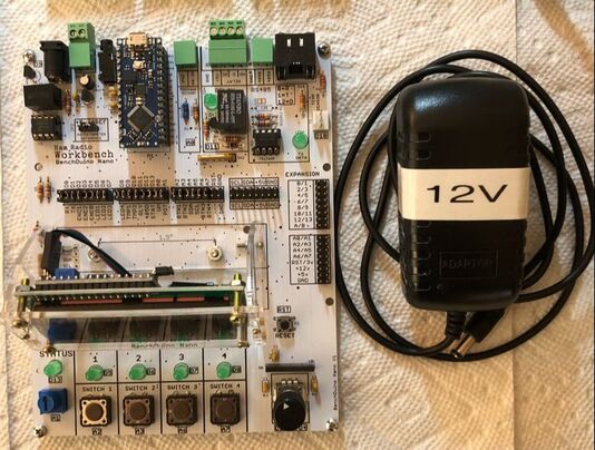
Prototyping Equipment
HRWB BenchDuino Nano This dev board is designed to make it easy to prototype projects using the Arduino Nano series of microcontrollers. The dev board includes...
|
|
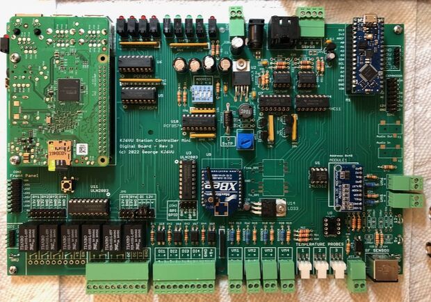
KJ6VU Station Controller Project Board
This is the current project in development. This is, hopefully, the final version of the PCB. All assembled and ready for testing. Features include:
|
PRO TIP: If there ever was a time to focus on that software-oriented project, this would the time. In my case my current projects are using RPI's and Arduino's so besides the PCB assembly, the majority of the project work is in the software and firmware development. Software development takes up no room except for your computer, a bag of Cheetos and a can of Mountain Dew.
Comparing Popular QRP Radios
There are so many exciting portable radios these days. I recently saw a YouTube video by Alan W2AEW who showed the new FX-4C radio from BG2FX Amateur Radios. I am the happy owner of an IC-705, Lab 599 TX-500 and an Elecraft KX2. I really like all of these radios but for different reasons. They are all great but each one has it's own sweet spot. With the new FX-4C I though it would be interesting to compare them. I don't have the new radio so all I can do at this point is to compare obvious physical attributes. When I get the new radio I will give it a more complete review.
So with the availability of so many new radios, why focus on this one? The simple summary is that it's about the same size and weight as the KX2 and TX-500, same output power, same bands, but at half the price. It also comes with a built in sound card which means it might just be a killer portable radio for digital modes.
Here are some of the key physical comparison points.
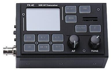
FX-4C
|
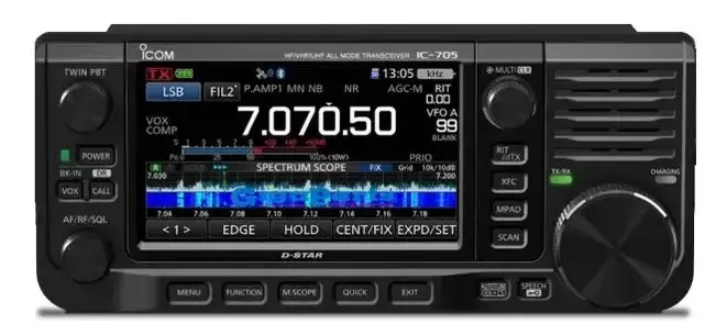
IC-705
|
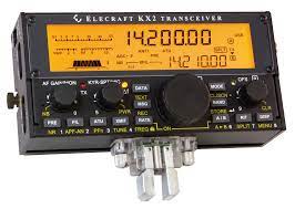
KX2
|
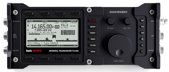
TX-500
|
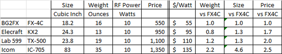
I know there are several comparison points that would certainly push you one way or the other but for typical HF operation, this is food for thought. For me personally I am a huge fan of the 705, TX-500 and the KX2 but for different reasons.
- If I were doing a backpack trip it would take the KX2.
- For a day trip on HF only I would take the Lab 599 TX-500
- For a day trip where I want maximum features including VHF/UHF the 705 is a the answer.
Icom IC-705 / Heil Headset Adapter
INTRODUCTION
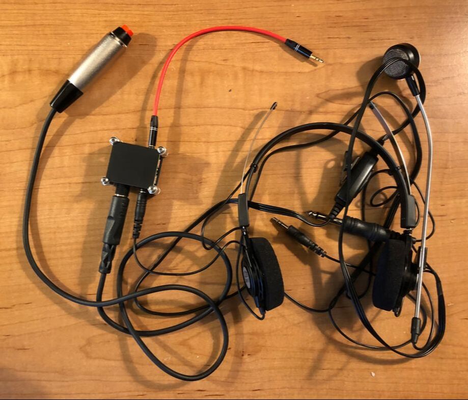
Sometimes you just need a little gadget that does not seem to exist anywhere so you gotta make one. I have been using my IC-705 lately and I really love this little radio. For field day I wanted to get all duded up and decided to hook up my Heil BM-10. This headset is super light weight and has a great mic. I standardized on the Heil connectors for all my radios using 3.5mm plugs for mic audio, 1/4" for PTT and 3.5mm for headphone audio. The question is how to adapt the BM-10 to the '705 ??? The phones just plug in but the pushbutton PTT switch and the mic plug need to get mixed together and reappear on a 2.5mm plug to go into the mic jack. Well, as it turns out, there is *NO* off the shelf adapter thing from Heil to do this. Really ??? Nope. OK, time to make one.
DETAILS
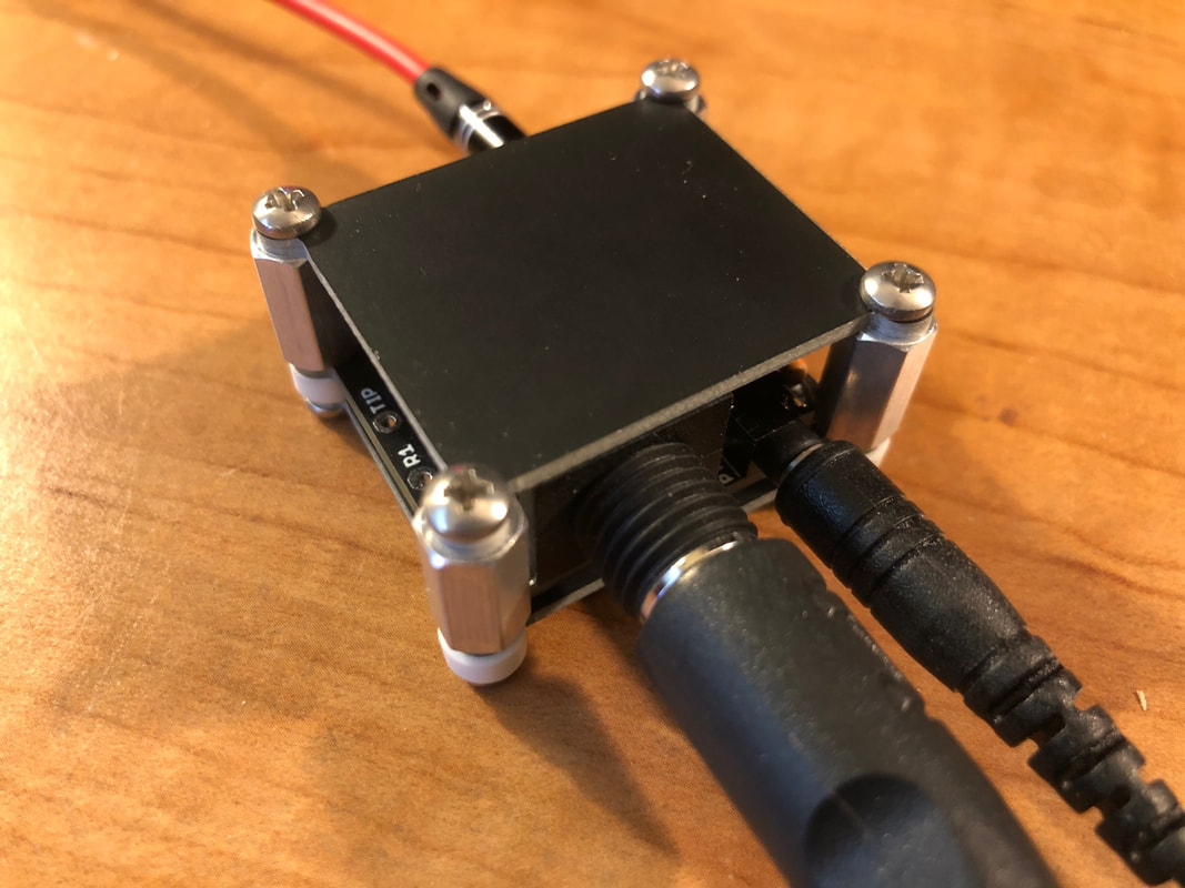
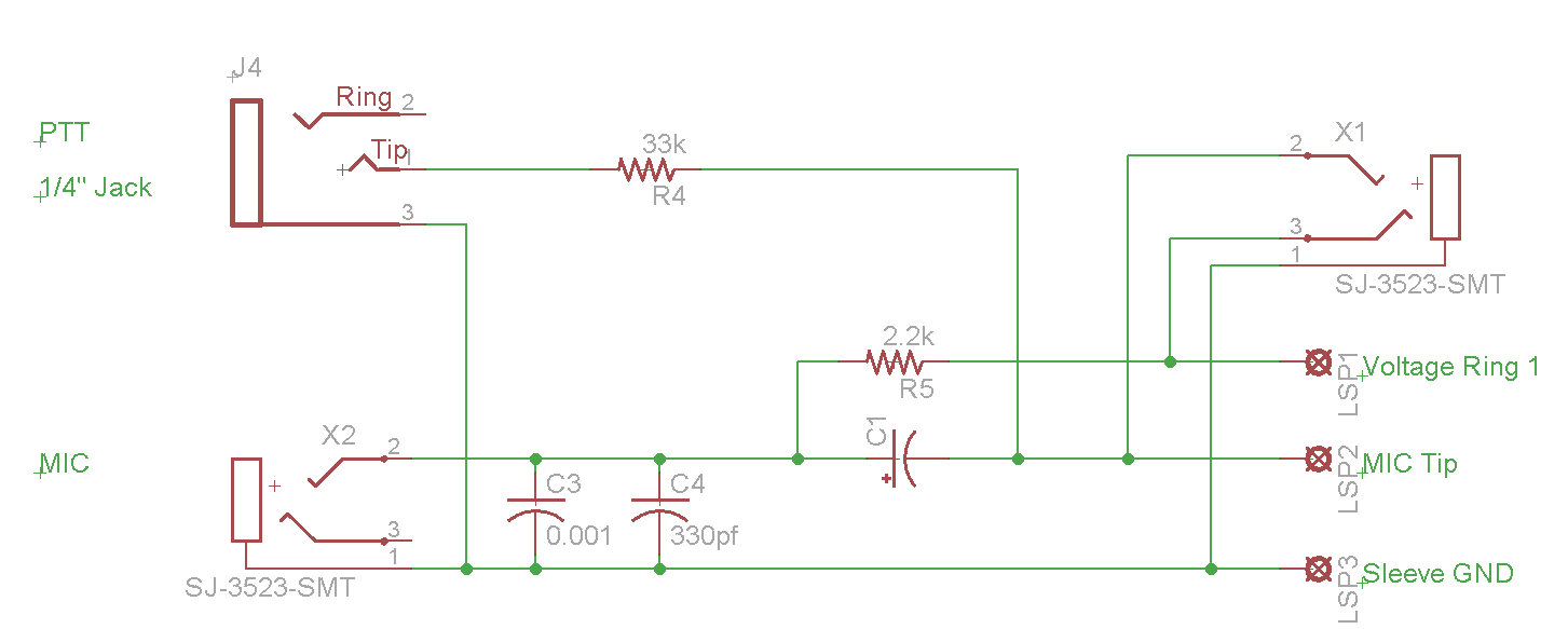
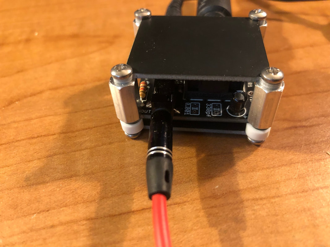
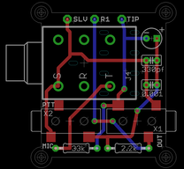
Here is the schematic, board layout done in Eagle and pictures of the completed adapter gadget. It's about 1" square and about 3/4" tall. The PTT pushbutton is a Switch craft hand held button on a cord that plugs into the 1/4" jack on my adapter. This way you can also use a stock Heil PTT trigger. The headset mic audio goes in on a 3.5mm jack. The output comes out the other side on a 3.5mm jack. You need a simple 3.5mm to 2.5mm pigtail that you can buy on Amazon for about $6. The connectors, resistors and capacitor are soldered to the middle PCB. There are blank PCB plates on the top and bottom to keep from shorting stuff out. Standoffs and screws keep it all together.
COMPONENT VALUES
BTW the two non-polarized capacitors are there for you to twiddle with values to see if you need one or not. I am running without either cap and it works fine. Just depends on your voice. Also resistor values are not super critical. I am using 39k instead of 33k and 2.7k instead of 2.2k because that is what I had on had. Works fine.
Sometimes you just need a little gadget that does not seem to exist anywhere so you gotta make one. I have been using my IC-705 lately and I really love this little radio. For field day I wanted to get all duded up and decided to hook up my Heil BM-10. This headset is super light weight and has a great mic. I standardized on the Heil connectors for all my radios using 3.5mm plugs for mic audio, 1/4" for PTT and 3.5mm for headphone audio. The question is how to adapt the BM-10 to the '705 ??? The phones just plug in but the pushbutton PTT switch and the mic plug need to get mixed together and reappear on a 2.5mm plug to go into the mic jack. Well, as it turns out, there is *NO* off the shelf adapter thing from Heil to do this. Really ??? Nope. OK, time to make one.
DETAILS
Here is the schematic, board layout done in Eagle and pictures of the completed adapter gadget. It's about 1" square and about 3/4" tall. The PTT pushbutton is a Switch craft hand held button on a cord that plugs into the 1/4" jack on my adapter. This way you can also use a stock Heil PTT trigger. The headset mic audio goes in on a 3.5mm jack. The output comes out the other side on a 3.5mm jack. You need a simple 3.5mm to 2.5mm pigtail that you can buy on Amazon for about $6. The connectors, resistors and capacitor are soldered to the middle PCB. There are blank PCB plates on the top and bottom to keep from shorting stuff out. Standoffs and screws keep it all together.
COMPONENT VALUES
BTW the two non-polarized capacitors are there for you to twiddle with values to see if you need one or not. I am running without either cap and it works fine. Just depends on your voice. Also resistor values are not super critical. I am using 39k instead of 33k and 2.7k instead of 2.2k because that is what I had on had. Works fine.
Eagle Schematic File
|
Eagle PCB Layout File
| ||||
KJ6VU Station Controller
The Station Controller hardware and software project to automate my home station and build infrastructure for remote station operation.
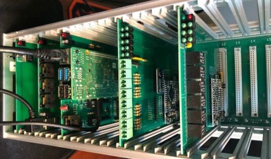
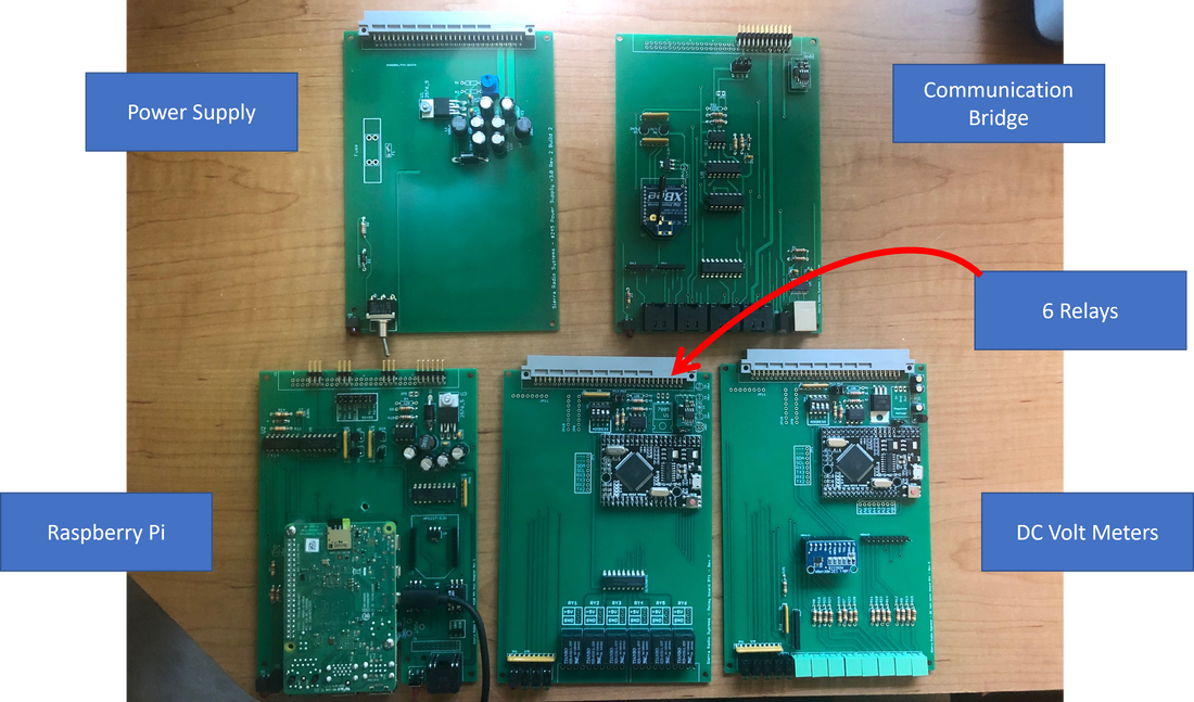
Station Controller Rack
The control rack is built in a Vector 3U subrack with a multislot backplane and a set of various plug in boards.
In the card cage the boards are...
In the card cage the boards are...
- Power supply board. Takes external 13.8v and routes it to the backplane and regulates to 8 VDC also on the backplane.
- Comm brige board. Provides RJ45's for external RS485 device connections and a USB connection.
- Raspberry Pi host adapter
- 8 channel voltmeter (4 channel single ended ADC and 4 channel differential 16 bit ADC)
- 6 relay dry contact control board
|
|
macro.exe - The Serial Control Program
macro.exe is a Windows program that, when invoked, will send a serial command or a string of serial commands in various formats to one or more serial ports. This lets you trigger an event from a Stream Deck or any other hotkey launcher and control the Station Control Rack hardware and various radios including Icom and Yaesu.
|
| ||||
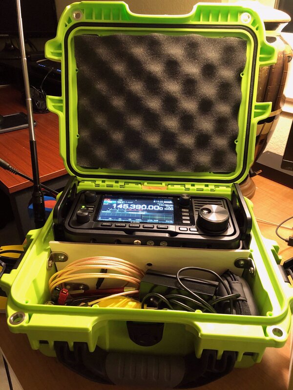
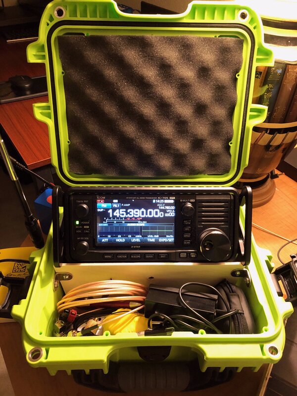
Packaging the IC-705 in a Nanuk 905 Case
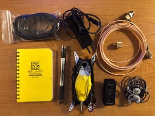
I found having the radio and a bunch of cables going to antenna tuners, batteries and other accessories made setting up the station in the field inconvenient. I decided to box up the radio and accessories into a case so I just need to connect an antenna, flip the case open, power up the radio and I am on the air. Here are pictures of the construction.
|
|
|
|
|
|
|
|
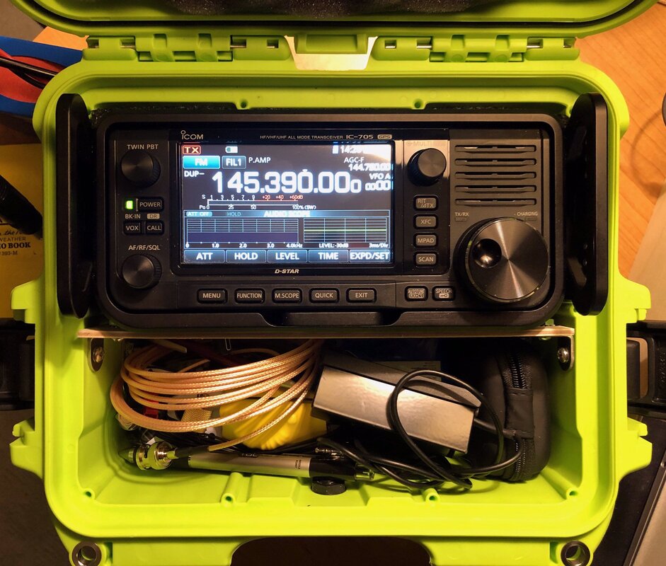
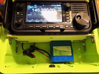
The box contains the radio mounted in a Peovi cage that includes handles. The radio is held in place by friction and when the case is closed and there is an optional screw hole in the wooden barrier for a 1/4" x 20 camera mounting screw. Under the radio is a thin 3mm thick piece of Baltic birch and under that is a MAT-705+ tuner.
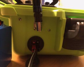
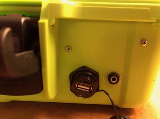
The left side of the case has a dual powerpole DC power connector for external power and a bulkhead mount BNC to BNC adapter. On the right side is a USB bulkhead pass through connector and a 3.5mm jack for an external paddle connection.
Internally there are cables from the USB pass through to the radio, 3.5mm jack to the key jack on the radio and a 3.5mm cable from the tuner jack to the tuner. The powerpole DC connector jack is connected to the radio and a pigtail under the shelf to the 3 Ah Bioenno LiFePo4 battery you see in the lower accessory compartment.
One really nice thing about this approach is that when the radio his horizontal for transportation it's useful for quick setup in that orientation. If you are going to be operating for an extended time and want to view the radio face on, you just pull the radio up and tip it forward and the handles rest on the wooden shelf.
One of the nice surprises of this approach is using the Icom VS-3 Bluetooth mic. This eliminates the coiled cord microphone and using Bluetooth ear buds eliminates a bunch of wires. The extra bonus is that the function buttons on the mic allows you to remotely tune the radio or map other functions to the buttons. Very nice !
This approach is super portable for taking the radio to the park or throwing it in the car. It's on the big and slightly heavy side for a SOTA event. I can stuff it into my Osprey day pack with room to spare but I would not call it light weight. It's OK but I would not want anything bigger and heavier. If I were going on a long hike or backpack trip where size and weight were the top consideration, I would rather take a KX2 which would come in at a fraction of the size and weight. But for a short hike up a hill this is a great setup.
Shopping List
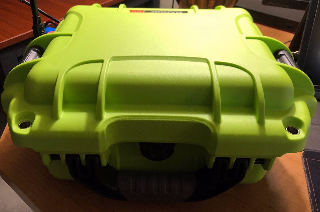
Nanuk 905 Case
Peovi roll cage
MAT-705 Plus tuner
Icom VS-3 Bluetooth microphone
Bose Bluetooth ear buds
3 Ah Bioenno battery
PackTenna random wire antenna
PackTenna mini RG-316 coax cable
Write in the rain notebook
The left side of the case has a dual powerpole DC power connector for external power and a bulkhead mount BNC to BNC adapter. On the right side is a USB bulkhead pass through connector and a 3.5mm jack for an external paddle connection.
Internally there are cables from the USB pass through to the radio, 3.5mm jack to the key jack on the radio and a 3.5mm cable from the tuner jack to the tuner. The powerpole DC connector jack is connected to the radio and a pigtail under the shelf to the 3 Ah Bioenno LiFePo4 battery you see in the lower accessory compartment.
One really nice thing about this approach is that when the radio his horizontal for transportation it's useful for quick setup in that orientation. If you are going to be operating for an extended time and want to view the radio face on, you just pull the radio up and tip it forward and the handles rest on the wooden shelf.
One of the nice surprises of this approach is using the Icom VS-3 Bluetooth mic. This eliminates the coiled cord microphone and using Bluetooth ear buds eliminates a bunch of wires. The extra bonus is that the function buttons on the mic allows you to remotely tune the radio or map other functions to the buttons. Very nice !
This approach is super portable for taking the radio to the park or throwing it in the car. It's on the big and slightly heavy side for a SOTA event. I can stuff it into my Osprey day pack with room to spare but I would not call it light weight. It's OK but I would not want anything bigger and heavier. If I were going on a long hike or backpack trip where size and weight were the top consideration, I would rather take a KX2 which would come in at a fraction of the size and weight. But for a short hike up a hill this is a great setup.
Shopping List
Nanuk 905 Case
Peovi roll cage
MAT-705 Plus tuner
Icom VS-3 Bluetooth microphone
Bose Bluetooth ear buds
3 Ah Bioenno battery
PackTenna random wire antenna
PackTenna mini RG-316 coax cable
Write in the rain notebook
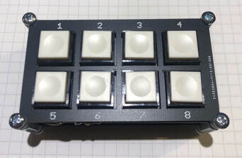
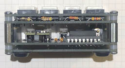
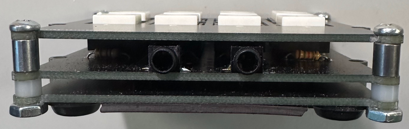
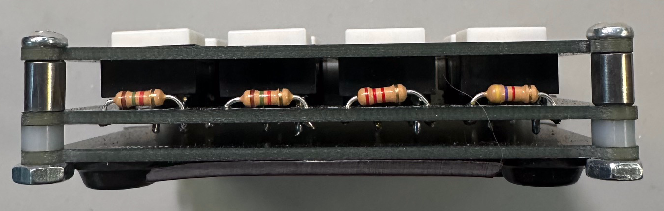
IC-705 Macro Button Board and Amp Keying Circuit
This handy accessory is a stack of 4 little PCBs. From top to bottom they boards are...
Version 1...
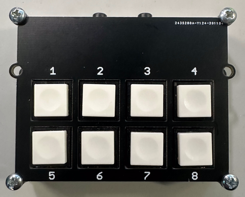
- Front panel to hide the parts below and label the switches 1 to 8
- Button board that holds the 8 push buttons and 8 resistors plus the interconnect header
- Connector board has the 5v regulator, relay, and all the connections to the radio and amplifier
- Blank board to protect the electronics from shorting to anything
Version 1...
|
|
|
|
|
Connections from left to right:
|
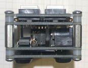
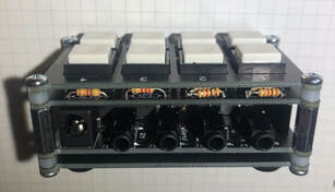
Version 2...
|
|
In version 2, the send keying output was removed and the whole assembly was made much lower. The two 3.5mm jacks allow the paddle connections to pass through the board. This way you can use the keypad by itself for voice or route the paddle through the board for CW.
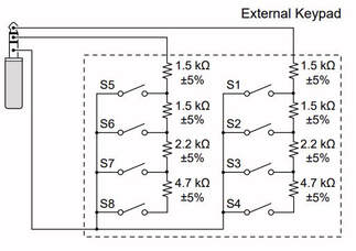
Icom's schematic for switches and resistor values implemented on the button board.
Icom IC-705 Keypad Schematic
Amplifier PTT Buffer Circuit
The buffer circuit uses a ULN2803 Darlington transistor array because it can switch up to 500ma per pin and has a very sensitive input that does not put excessive load on the keying circuit from the radio. This is a bit of overkill because you can do the same thing with a few discrete transistors but this also gives you additional buffered control lines. You can use it to switch status LEDs, or other control relays. Even if you don't use the extra transistors in the package it's cheap and works great.
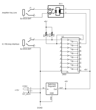
Parts List
- ULN2803 transistor array chip
- HE3621A0510 5v Reed relay
- 2x 10k pullup resistors
- 2x 3.5mm stereo jacks
- 5v Voltage regulator (Switching regulator OKI-78SR-5/1.5-W36H-C or linear regulator 7805)
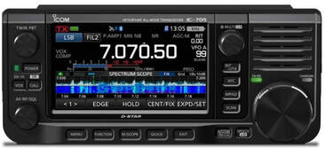
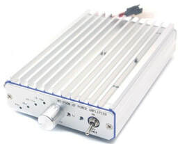
IC-705 + MX-P50M Amplifier
|
|
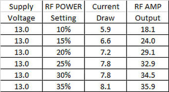
The MX-P50M is a nice, low cost HF amplifier, that can boost your 705 to about 30+ watts for field operation with a typical LiFePo4 battery. Below is the power consumption vs RF power output for a given drive level. When you set the radios output power percentage, that number is the percentage of 10 watts. This means, a setting of 20% means the radio will put out 20% of 10 watts which is, of course, 2 watts. The missing feature to make this work is a buffer circuit to take the radios "SEND" output and use it to key the amplifier. This amp does not have RF sensing PTT so you need to manually switch it or use a circuit like the keying amp circuit project above.
Bioenno 3Ah LiFePo4 Battery Discharge
I wanted to test the Bioenno 3Ah battery with a constant load to measure its capacity. I connected my battery to my programmable load, set the constant current draw to 2A and here are the results. I did not run it all the way down until the battery shut off. I was looking for when the battery hits 12.5v which is where the RF power output starts to drop. That turns out to be 1 hour with a constant draw of 2 A before power starts to drop. The current draw is about 500 ma on receive when everything is turned on. Given all this, I think you can expect a good 3 or more hours of use and very likely much more depending on the radio configuration and your operating mode and style. For about $50 this battery is ideal for light weight applications like SOTA when you want maximum power, minimum weight and plan to only operate for a few hours. If you *really* want to minimize weight and size, I would use the Elecraft KX2, but the Icom IC-705 is really a beautiful radio to operate.

|

|
Icom IC-705 RF Power vs Supply Voltage
I have started to characterize the voltage vs power output of the IC-705 and thought I should share my findings here.
The radio runs on the internal HT size battery up to 5 watts which is fine for casual listening or the odd VHF/UHF contact but when I want to operate HF, I really want the full 10 watts or at least the option to bump up to 10 watts. With that in mind there were several questions to answer. What is the relationship between supply voltage and power out? At what voltage does the radio drop into low power mode? Which battery would be best for field use?
To answer these questions I did some basic characterization on the bench. First measuring the output power on a bench supply then I tested it with a PowerFilm Solar 12 volt Lithium Ion battery and a Bioenno LiFePo4 battery. Here are results.
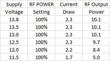
RF Power Measurements with a Power Supply
RF output power was set to 100% and the power supply voltage was swept from 13.8v down to 11.5v. I was looking at the RF output vs supply voltage and to see where the radio would drop into low power mode.
RF output power was set to 100% and the power supply voltage was swept from 13.8v down to 11.5v. I was looking at the RF output vs supply voltage and to see where the radio would drop into low power mode.
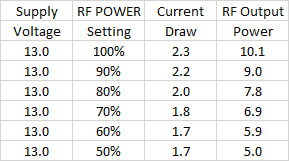
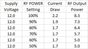
RF Power Measurements with a Power Supply Set To a Fixed Voltage
The power supply voltage was fixed to 13.0 and 12.0 volts and then the power output was swept from 100% down to 50%. You can see from the charts what the current consumption measured and the RF output power.
|
|
RF Power Measurements with a PowerFilm Light Saver Max Battery
The Light Saver Max is a really cool battery that has a built in solar panel. The battery appears to have a very flat discharge curve and a capacity of about 5 Ah. I am guessing its a set of 18650 LiIon batteries. The battery has 2 USB jacks and a 12v jack. You can charge it from a wall wart or the built in solar panel that is somewhere around 7-10 watts.
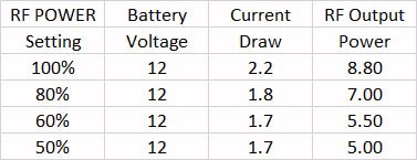
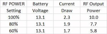
RF Power Measurements with a Bioenno LiFePo4 Battery
This is the most popular type of battery these days for ham radio applications. You can see from the chart below with one additional volt makes a difference. The test was run with a 12 Ah Bioenno battery but the voltage and discharge curve is the same regardless of the battery size. The bigger the batter the longer the run time.
Summary
Both batteries would work well and the weight and volume of the batteries are similar at the same current capacity. The PowerFilm Light Saver Max is a novel design with multiple cool features where the Bioenno is just a battery and built in battery management system. At the same current capacity, the Bioenno is 1/3 the price of the Light Saver so if you don't need the USB jack, flashlight or solar panel, the Bioenno is the hands down winner. You get 10% more RF power out at 13/ the cost.
You could run the 705 from a traditional sealed lead acid battery and it would work just fine until the terminal voltage sagged to about 11.5 volts when the radio reverts to low power mode and limits itself to 5 watts. You would also suffer lower power output as the voltage drops over time from 13.8 down to below 12v when you should stop discharging it.
These days there is really no better battery than a high quality LiFePo4 battery when you need to power a 12v (13.8v) radio and Bioenno is a top pick. They have great service, reasonable prices, and the batteries come with an Anderson PowerPole load connector and a 2.1mm DC barrel connector for charging. BTW pick up the AC charger for about $25.
There is also a DC / DC charger so you can charge them safely from the car or another 12 source for about $99.
Game over. Just buy a Bioenno battery. The 3 Ah is a really nice super small battery that would be fine for a brief outing.
A bit larger battery, like the 4.5 or 6 Ah battery would be perfect for an afternoon or maybe even a weekend of operating.
If I was powering an external amplifier, charging my phone, or running other accessories and I was not hiking with it, I would get a 12 Ah battery. They are all very good. Just pick the size and capacity that works for you.
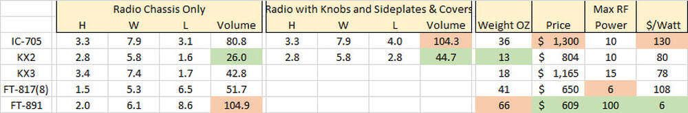
Physical Comparison of Popular QRP and Portable HF Radios
I wanted to do an objective comparison of the sizes, weights, power, and other factors. This highlights the pros and cons at least from a physical point of view. Obviously there are many feature differences between these radios but size/weight/power is a first order consideration when you are considering what radio to pick. The best in class is highlighted in green and worst in red. I have personally owned and used all of these radios except the FT-818. I owned an FT-817 which is more less the same thing. Each one has strengths and weaknesses and I think each of these are very good radios depending on what you are trying to do.
You can easily build a case for each of these radios depending on what you are trying to do.
You can easily build a case for each of these radios depending on what you are trying to do.
Hamclock - 1600 x 960 Setup
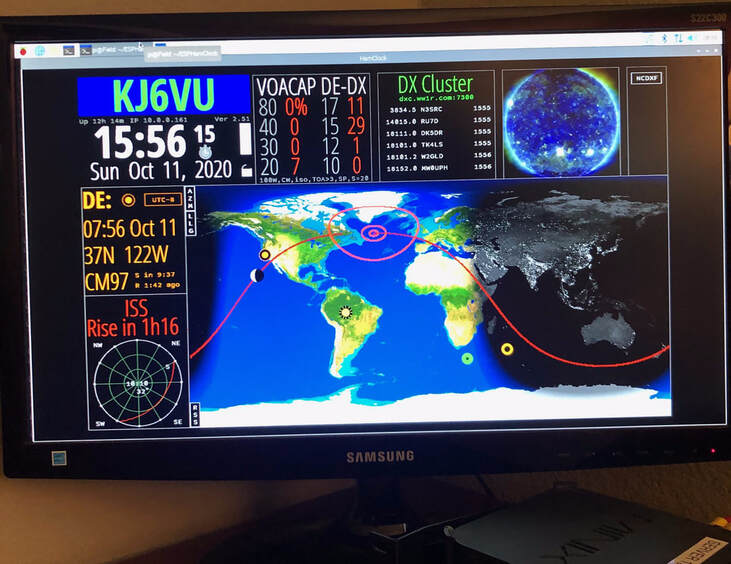
!Hamclock is a great linux application that can display a world map, propagation, satellite passes, time, etc. The software is free and runs on a Raspbery Pi. Think of it as a poor man's Geochron. I started using Hamclock because it was part of the Build-A-Pi image by Jason KM4ACK. This is a wonderful ham radio image with all the popular programs. I highly recommend it. You can check out Jason's great YouTube channel and see more on Hamclock.
When you run Hamclock on the Build-A-Pi image, the size of the Hamclock display is fairly small. I want to use it as a full screen image but it was not obvious how to make this work. Digging around on the Clear Sky Institute web site, I finally figured it out.
The first step is to install the Hamclock program. If you are using the Build-A-Pi image, you already have it installed.
If you don't have it installed, these steps will install the software in /home/pi/ESPHamClock
cd
curl -o ESPHamClock.zip http://www.clearskyinstitute.com/ham/HamClock/ESPHamClock.zip
unzip ESPHamClock.zip
cd ESPHamClock
At this point you need to "make" the program with the screen size you want.
There are various sizes supported. If you just type "make" you will see the options for different screen sizes.
For me the 1600x960 seems like a good size for a 21" HDMI monitor I was not using. Enter this command to create the program with the 1600x960 screen size...
make -j 3 hamclock-1600x960
To run the program execute this command from the /home/pi/ESPHamClock folder.
sudo ./hamclock-1600x960
There you go ! A super useful large screen display with essential station info. For the cost of a Raspberry PI and an old HDMI monitor, it's a great alternative to the Geochron, especially if you can scavenge the Pi and display from the junk box !