Ham Radio Workbench Podcast
  • HOME
  • Podcast
  • Projects
    • DC Power Strip >
      • DC Power Strip Assembly
    • BenchDuino >
      • BenchDuino Builder's Notes
    • K6BEZ Antenna Analyzer
    • 4-Port Coax Relay
    • QRP Smarty Load
    • QRP Dummy Load
  • Articles
  • Blogs
  • Shop
  • Resources
  • INDEX
  • About
  • Contact

25 Watt QRP Dummy Load Project

Introduction​

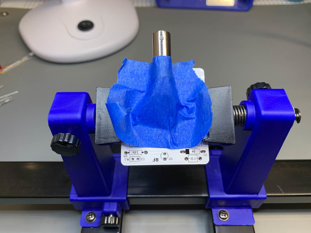
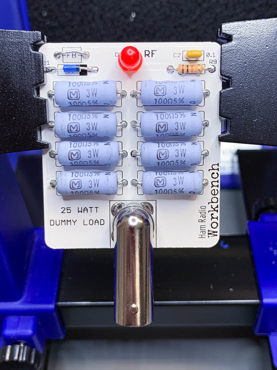
A perfect introduction to through-hole soldering, the Ham Radio Workbench QRP Dummy Load project rated for short bursts of up to 25 Watts with an LED that indicates the presence of RF. 

​Caution! - This unit will get hot even with brief RF exposure (15 watts for 60 second resulted in 200F temperatures).  Use only in short bursts and with good ventilation and maybe a small fan to dissipate heat!
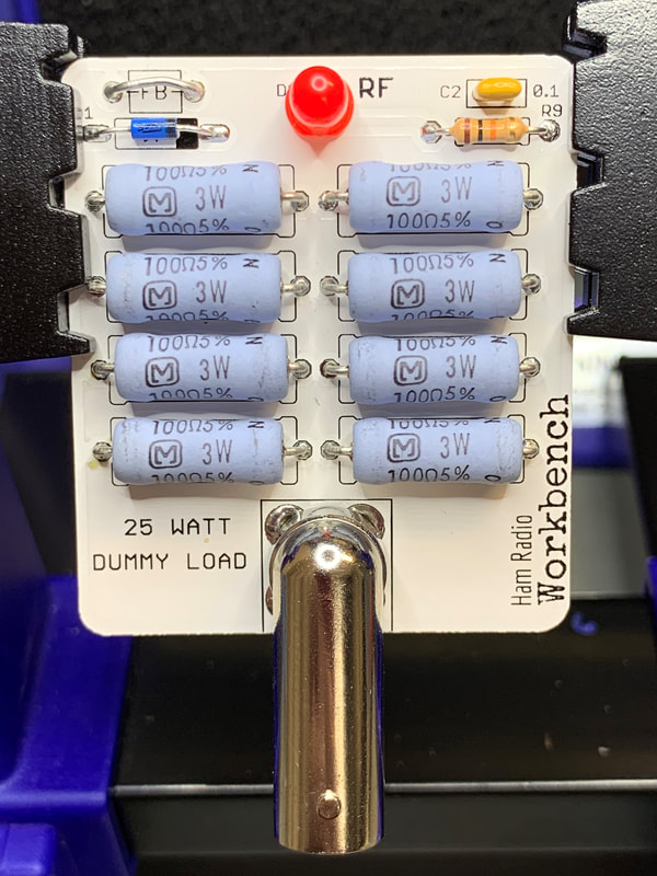
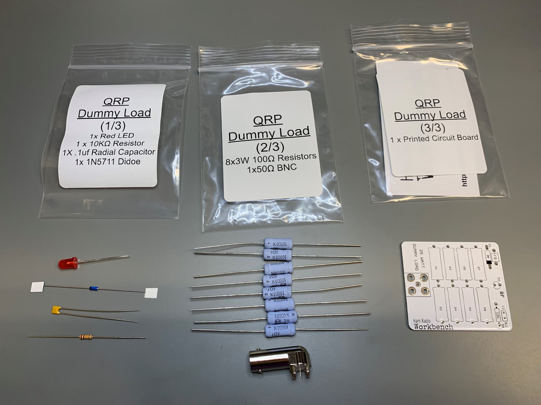
Parts / Supplies

  • QRP Dummy Load Materials List (BOM) in Excel Format
Type
Part
Description
Digikey Part Number
Qty
Capacitor
C2
​0.1" spaced dipped mono 10%
0.1
​478-3192-ND
1
Diode
D1
​Signal Diode (1N5711)
1N5711
​497-2499-1-ND
1
Diode
D2
​LED
Value
​732-5016-ND
1
Resistor
R1-R8
​3 Watt 100 Ohms
100
​P100W-3CT-ND
8
Resistor
R9
​1/4 Watt 10k 5%
10K
​10KQBK-ND
1
Connector
Value
BNC Right Angle Connector
​A97569-ND
1

Buy Now

Documentation

To assemble this project, you will need the following tools and supplies:
  • Temperature controlled soldering iron (capable of 425C operation)
  • Small "chisel" soldering iron tip
  • Rosin core solder
  • Masking Tape
  • Soft wire cutters (for trimming component leads)

To make the project even easier, the following items are helpful
  • Work piece holder (Panavise Junior, Atten holder, etc)
  • Rosin flux pen / needle bottle

General Guidelines
  • Begin will a clean, well-tinned soldering tip
  • When soldering, make sure to place as much of the flat part of the chisel tip against the solder pad as possible.
  • For lead bearing solder, solder at a temp of 375C (ish)
  • Use flux liberally at the solder joint
  • Keep the tip of your iron clean at all times using a wetted sponge and if available, a brass tip cleaner.


STEP 1

Begin by placing the BNC Connector in its position on the top of the board (the side with the silk screen).  Use masking tape to hold the BNC connector in place.
Picture
STEP 2

First, to tack the BNC connector to the board, you will solder the center pin of the BNC connector.
Picture
STEP 3

Next you will solder the remaining for pins on the BNC connector.  Because this high quality BNC connector has a high thermal mass, you will need to turn the soldering iron's temperature up to 425C or greater.  Be patient as heat builds up in the BNC connector and make sure not to accidentally touch it!
Picture
STEP 4

Next, we will populate the board with discrete components.  When inserting leaded through-hole components into the board, make sure to make good right angle bends of the leads.

For the next steps, you can turn the soldering iron temperature back down.
Picture
STEP 5

Start by soldering the large power resistors to the board, doing one at a time.  When inserting a leaded component, you can bend the legs out at 45 degree angels to keep them in place as you solder. 

The orientation of the power resistors does not matter.
​
You will solder 8 power resistors total.
Picture
STEP 6

As each component is successfully soldered to the board, inspect that the solder has adhered to the pad and the component and look for a dull sheen to the solder, not a shiny ball.  Trim the leads with the cutters and make sure to save at least one lead for a future step.
Picture
STEP 7

Next, install and solder the diode.  Note that the black band on the diode should be aligned with the black band of the D1 silk screen.
​
Picture
STEP 8

Using one of the trimmed leads from earlier, short the two pads in the FB box above the diode.
Picture
STEP 9

Install and solder the red LED in D2.  Note that there is a flat side of the plastic housing that should be aligned with the flat side of the silk screen image.
Picture
STEP 10

​Install and solder the resistor in to R9.  The orientation of this part does not matter.
Picture
STEP 11

Install and solder the ceramic capacitor in to C2.  The orientation of this part does not matter.
Picture
STEP 12

Congratulations, you have completed assembly of the QRP Dummy Load.  When a signal is present on the input, the LED should glow.  If you do not see the LED or your radio complains, double check your solder joints of all connections.
Picture
Brandmeister Talkgroup 31075
©2016-2020 Ham Radio Workbench, All Rights Reserved
Connect on Brandmeister Talkgroup 31075