Step By Step Assembly Instructions
You will need the following hand tools and supplies
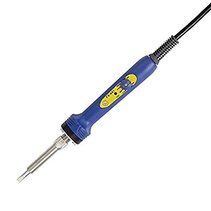
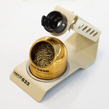
You can assemble the power strip with a common soldering iron but we recommend a high temperature iron with a large chisel tip. The reason is that you will be soldering the connectors and fuse holders to a large copper trace. The copper is 2oz weight, twice the thickness that you normally find on PCBs, and that copper will absorb a lot of heat. With that in mind, we highly recommend using an iron like the Hakko FX-601. We also recommend the Hakko 633-01 soldering iron holder and cleaning wire pot (599B). We also recommend high quality solder like Kester 63/37 or Ersin Multicore solder.
You will need the following hand tools and supplies
- Soldering iron and solder (Hakko FX-60L)
- Wire cutters (Hakko CHP-170)
- Philips screwdriver
You can assemble the power strip with a common soldering iron but we recommend a high temperature iron with a large chisel tip. The reason is that you will be soldering the connectors and fuse holders to a large copper trace. The copper is 2oz weight, twice the thickness that you normally find on PCBs, and that copper will absorb a lot of heat. With that in mind, we highly recommend using an iron like the Hakko FX-601. We also recommend the Hakko 633-01 soldering iron holder and cleaning wire pot (599B). We also recommend high quality solder like Kester 63/37 or Ersin Multicore solder.
|
|

|
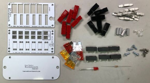
Step 1 - Inventory your parts
3 PCBs
6 red and 6 black PowerPole shells
12 PowerPole flat pins
6 fuse holders
6 fuses
1 LED
1 Resistor
4 hex standoffs
4 1/2" long 4-40 screws
4 1/4" long 4-40 screws
4 Nylon spacers
|
Step 2 - INstall the fuse holders. Tip: Place the fuse holders in the main board, cover the fuse holders with a stiff piece of cardboard, flip the board, place the board upside down with the cardboard side down on the table. Gently slide the board out from under the PCB. Hopefully, all the fuse holders are under the board and the pins are up ready for soldering. Use a large tip, high temperature soldering iron. |
|
|
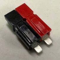
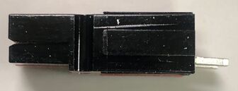
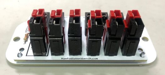
Step 3 - Assemble the PowerPole shells and insert the pins. You know when they are inserted properly because they *click* when inserted. |
|
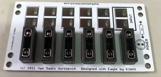
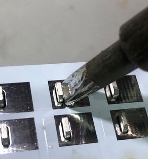
Step 4 - Solder the PowerPole connectors. Make sure you use a good amount of solder. The solder will easily flow down into the slots in the PCB. |
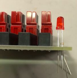
Step 5 - Solder LED and resistor.
Install the power LED. The LED, like any diode, is polarized so the orientation makes a big difference. The outline of the LED has a round side and a flat side. Make sure the LED shape matches the silkscreen outline on the board.
You can also double check by making sure the longer of the two LED leads is pointing inward toward the fuse blocks.
Then install the 1k resistor and clip the leads off of both parts on the bottom.
|
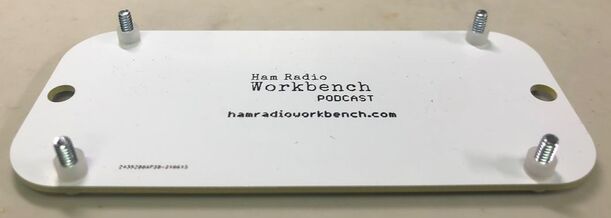
Step 6 - Install bottom board and mounting screws. Place the 4 long screws through the four holes in the corners of the bottom (flange mounting) board. Slip a nylon spacer over each screw. |
Step 7 - Set the connector board in place.
Slide the connector board over the four screws poking up form the bottom board.
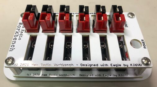
Step 8 - Install standoffs and top plate.
Screw on each of the 4 standoffs to the screws poking through the main connector board.
Turn the standoffs so they are finger tight.
You can then flip the board over and tighten the screws with a screwdriver.
Then slip the top plate over the connectors and align the board corner holes with the standoffs.
Screw in the 4 1/4" long screws through the top plate.
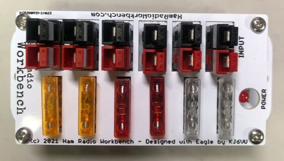
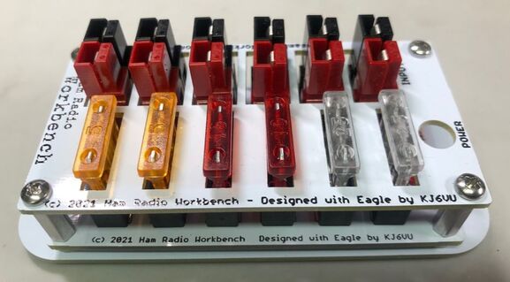
Step 9 - Install fuses
Insert the ATC Fuses through the top plate slots and into the fuse sockets.
We recommend inserting the fuses by current rating from left to right as follows...
5A - 5A - 10A - 10A - 20A - 20A
With this configuration you will have the input circuit fused at 20A, and the closest outlet also fused at 20A.
The board is rated for 20 amps. Prolonged use at 20 amps may cause the board to heat so be careful not to run the board too hot.
|
Step 10 - Enjoy your creation ! Grab a coffee, sit back and admire your handy work. You have made a super useful station accessory ! You can optionally install the outlet strip in a fixed position by screwing the bottom plate to a wall, box or any convenient flat surface. The LED will glow when 12 VDC is applied to the input jack. |