Ham Radio Workbench Podcast
  • HOME
  • Podcast
  • Projects
    • DC Power Strip >
      • DC Power Strip Assembly
    • BenchDuino >
      • BenchDuino Builder's Notes
    • K6BEZ Antenna Analyzer
    • 4-Port Coax Relay
    • QRP Smarty Load
    • QRP Dummy Load
  • Articles
  • Blogs
  • Shop
  • Resources
  • INDEX
  • About
  • Contact

12V DC Power Strip Project

Introduction​

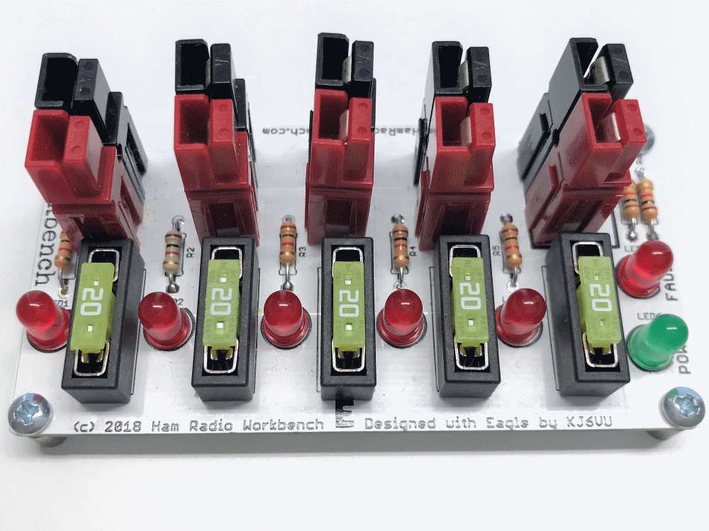
The Ham Radio Workbench 12V DC Outlet Strip allows you to share a single 12V power source with up to four other devices. 

This board is designed to support communication activities using a single 100 Watt HF radio, which will not operate at 100% duty cycle at full power, or a single 50 Watt FM VHF/UHF Radio that draws approximately 16A at 13.8VDC in QSOs.

This project features:
  • Designed for Anderson Powerpole Connectors
  • Operational Maximum Current Limit - 25 Amps @ 12V nominal total across all ports
  • Four fuse holders that accept standard or low profile ATC fuses
  • Polarity indicator for the 12V input to verify that your source is wired correctly
  • An LED will light to indicate when a load is connected to an output port with a blown fuse

Documentation

  • 12V DC Power Strip Assembly Manual
  • 12V DC Power Strip Materials List (BOM) in Excel Format

!!!CAUTION!!!
It is not recommended to operate at the Operational Maximum Current of 25A at 13.8VDC for periods longer than 5 minutes, as the copper traces of the 12V DC Outlet Strip can become hot, exceeding temperatures of 150F after an extended period (5 minutes or more) of constant 25A current draw.  Temperatures can approach 200F when a constant 25A at 13.8VDC are drawn for periods of 10 minutes or more.  

We designed this project to use 14 gauge solid core copper wire (not stranded) terminated with standard 30 Amp power poles - no PCB mounts required! 

PLEASE NOTE!
​
This project is intended to be completed with Solid Core 14 Gauge Wire-it eliminates the possibility of shorts due to strands and the Powerpoles will have a more solid mechanical connection to the board.  If you decide to proceed with stranded, do so at your own risk as it will be CRITICAL to ensure that no strands are touching one another.  Also, Powerpoles mounted with stranded wire may not be as mechanically sound on the board as solid.
  1. Begin by cutting two individual lengths of 14 gauge solid copper wire, 2"-3" in length (the shorter the length that you're comfortable working with, the better).  If using 2-conductor wire, separate the pair in to individual wires.
  2. Carefully remove the insulation from each strand of wire so that you are left with two lengths of bare copper wire.
  3. Terminate each of the wire lengths with 30 Amp Anderson Powerpoles, and install the terminated wires in the plastic housings.
  4. Run the end of the wire in the black housing through the hole on the side of the board where "GND" is printed inside the "Input" box.  Leave a little slack, as you will need it to join the Powerpoles - If using stranded wire, take extra care to make sure that no loose strands fly away from the copper wire.
  5. Run the end of the wire in the red housing through the hole on the side of the board where "12V" is printed inside the "Input" box.  Leave a little slack, as you will need it to join the Powerpoles - If using stranded wire, take extra care to make sure that no loose strands fly away from the copper wire.
  6. Attach the two Powerpole housings together and pull the excess wire tight through the boards so that the Powerpoles sit as flush with the board as possible - if using stranded wire, take extra care one final time to verify that there are no loose strands between wires which could cause a short circuit.
  7. With the Powerpoles pulled tight against the board, flip the board over and solder the wire to the connection point in the PCB - make sure you have a good solder point and that the mounting point fills completely with solder.
  8. Once the soldering is complete, cut the excess wire away from the PCB
  9. Inspect your work and apply more solder if necessary.

Parts / Supplies

  • Digikey Shopping Cart for 12V Power Strip parts and components
  • 10 Pack of 30A Anderson Powerpole Housings and Connectors
  • 3D Printed Case by Rocket City 3D

Buy Now

Benchduino PCB Bundle

$50.00

Sold out

Shop
Ham Radio Workbench 12V DC Power Strip PCB
Brandmeister Talkgroup 31075
©2016-2020 Ham Radio Workbench, All Rights Reserved
Connect on Brandmeister Talkgroup 31075